An Information to Project Specification for Meteorological Sensors
A well-defined project specification for meteorological sensors is essential for maximizing the efficiency and performance of solar energy systems. By following industry standards, choosing the right types of meteorological sensors, and establishing reliable calibration and maintenance procedures, stakeholders can ensure accurate data collection and better decision-making in their solar energy optimization projects.
Standards Compliance for Meteorological Sensors
As a part of weather monitoring station, the meteorological sensors with all necessary software and hardware are required to be integrated with a monitoring system to enable the implementation of meteorological data. Each meteorological sensor shall meet the standards mentioned below.
The meteorological sensors shall be dimensioned to follow the IEC 61724-1:2021 standard. The Photovoltaic Power Plant (PVPP) should be monitored according to Class A (High accuracy) as of Table 1 from the mentioned standard. The total number of each sensor installed should be aligned with the requirements of Table 2 and Table 3. It is therefore important that the IEC 61724-1 published in 2021 is in place, as there are key differences with former versions.
General Technical Requirements of Meteorological Sensors
Among the different ambient parameters, only those stated in IEC 61724-1:2021 Table 2 (Class A system) shall be considered by the Contractor, in quantity stated in Table 3.
Irradiance Sensors – Pyranometers
There should be two types of solar irradiance sensors installed onsite: pyranometers and silicon reference cells. The combination of these two types of sensors offers high resilience for monitored data validation. To check the difference between these two types of Irradiance sensors, you can check the following article: https://www.sevensensor.com/what-is-the-price-of-irradiance-sensor-and-pyranometer
The Irradiance Sensors shall meet the requirements of Table 4 according to sensor type, as stated below.

Photo2: Irradiance Sensor Requirements
Thermopile Pyranometers

Photo3: Thermopile Pyranometer
Pyranometers offer a wider light spectrum reading compared to reference cells. Pyranometers shall be spectrally flat Class A for front side POA and GHI and Class C or better for rear side POA and complying with ISO 9600. Accuracy shall maximum be within ± 2% over a range of temperature of -40°C to +70°C, compared to the calibration temperature. Data values delivered by the pyranometer should be temperature corrected.
Communication with the datalogger is done through RS485 Modbus interface. The pyranometer shall integrate protection against over voltage, reversed polarity and short circuiting. The electrical connection for the meteo sensor shall be done with an integrated cable or an IP67 rated connector.
When bifacial modules are used, at least one pyranometer shall be measuring GHI and at least two (one for front side (Class A) and one for rear side (Class C or better) for POA irradiance.
Reference Cell Irradiance Sensor

Photo4: Irradiance Sensor
Reference Cell Irradiance Sensors are made of the same technology as the PV modules. These sensors are a decent budgetary alternative to pyranometers as they are a robust and reliable solution for measuring solar irradiance levels while offering specific advantages for PVPP monitoring, for instance. Accuracy of the reference cells shall be of 2% at 1000W/m2, which make it Class A as per IEC61724-1:2021. Their operating temperature range shall be wide, such as -35 °C to 80 °C market standards.
PV module Temperature Sensors
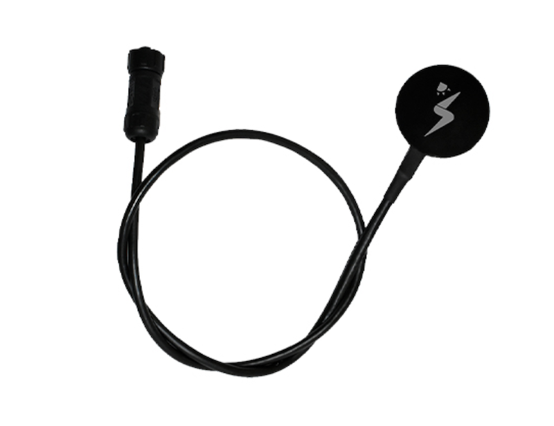
Photo5: Back of Module Temperature Sensor
The sensor type and attachment method can have significant impacts on the measured temperature, leading to significant measurement errors. These errors are affected primarily by the contact between the sensor and the PV module's rear surface, the amount and type of insulation placed over the sensor, and the amount and type of adhesive used. Preference should be given to flat probes designed specifically for long-term surface measurements. Temperature sensors shall have a measurement resolution ≤ 0.1 °C and uncertainty ± 1 °C or better.
The location of the PV module temperature sensors should be the center of a cell close to the center of the PV module (from the rear side), avoiding boundaries between cells. For bifacial PV modules, rear-side temperature sensors and wiring shall obscure < 10 % of the area of any cell, and wiring should be routed in between cells when possible.
Ambient Temperature Sensors

Photo6: Ambient Temperature Sensor
Although some irradiance sensors can measure ambient temperature, specialized ambient temperature sensors should be used for that purpose, as they offer higher accuracy.
Ambient air temperature is measured by means of temperature sensors located in solar radiation shields which are ventilated to permit free passage of ambient air. The Ambien Temperature sensors shall have a measurement resolution ≤ 0.1 °C and uncertainty ±1 °C or better. The sensors should be placed at least 1m away from the nearest PV module and in locations where they will not be affected by thermal sources or sinks, such as exhausts from inverters or equipment shelters, asphalt or roofing materials, etc.
Wind Speed and Wind Direction Sensors

Photo7: Wind Speed Sensor
Wind speed sensors are used for estimating PV module temperatures and heat transfer losses. They may also be used for documenting warranty claims related to wind-driven damage. Wind measurement equipment should not shade the PV system at any time of day or year and should be located at a point that is sufficiently far from obstructions. Wind speed sensor’s measurement uncertainty shall be ≤ 0,5m/s for reading wind speeds ≤ 5m/s, and ≤ 10% for reading wind speeds greater than 5m/s as per IEC61724-1:2021.
Soiling Ratio

Photo8: Soiling Sensor
Soiling ratio is a property of the PV array cleanliness condition. High soiling induces PVPP performance loss and threatens the performance guarantees. To monitor soiling ratio, a soiling sensor is used which compare two reference cells. One cell is routinely cleaned (according to O&M principles, but minimum once a week) and the other cell soils naturally at the same rate as the PV array. Detail methods for implementing this approach are described in detail in ANNEX C of IEC 61724-1:2021.
Calibration requirements
All the meteorological sensors to be supplied shall have valid and traceable calibration certificate. Each pyranometer shall be recalibrated at an interval not more than two years (according to ISO 9847) and all other meteo sensors shall be recalibrated at an interval not more than four years.
For Class A systems, sensors are to be recalibrated every 2 years, or more frequently as advised by the manufacturer. For Class B systems, recalibration of sensors should follow the manufacturer's recommendations.